A brief history about the development of aviation checklists used in aircraft today
October 30, 1935 Wright Field, Dayton, Ohio
The final phase of aircraft evaluations under U.S. Army specification 98-201 (July 18, 1934) was to begin. Three manufactures had submitted aircraft for testing. Martin submitted their Model 146; Douglas submitted the DB-1; and Boeing submitted their Model 299. Boeing, a producer of fighters for U.S. Navy aircraft carriers, had little success in commercial airliners or bombers for the U.S. Army Air Corps.
Boeing’s entry had swept all the evaluations, figuratively flying circles around the competition. Many considered these final evaluations mere formalities – talk was of an order for between 185 and 220 aircraft. Boeing executives were excited – a major sale would save the company.
At the controls of the Model 299 this day were two Army pilots. Major Ployer P. Hill (his first time flying the 299) sat in the left seat with Lieutenant Donald Putt (the primary Army pilot for the previous evaluation flights) as the co-pilot. With them was Leslie Tower (the Boeing Chief Test Pilot), C.W. Benton (a Boeing mechanic), and Henry Igo (a representative of Pratt and Whitney, the engine manufacturer).
The aircraft made a normal taxi and takeoff. It began a smooth climb, but then suddenly stalled. The aircraft turned on one wing and fell, bursting into flames upon impact.
Putt, Benton, and Igo – although seriously burned – were able to stagger out of the wreckage to the arriving safety crews. Hill and Tower were trapped in the wreckage but were rescued by First Lieutenant Robert Giovannoli, who made two trips into the burning aircraft to rescue both men.
Both men later died of their injuries. Lt. Giovannoli was awarded the Cheney Medal for his heroism that day, but he died in an aircraft accident before receiving it.
The investigation found “Pilot Error” as the cause. Hill, unfamiliar with the aircraft, had neglected to release the elevator lock prior to take off. Once airborne, Tower evidently realized what was happening and tried to reach the lock handle, but it was too late.
It appeared that the Model 299 was dead. Some newspapers had dubbed it as ‘too much plane for one man to fly.’ Most of the aircraft contracts went to the runner-up, the Douglas DB-1. Some serious pleading and politicking by Air Corps officers gave Boeing a chance to keep the Model 299 project alive – 13 aircraft were ordered for ‘further testing’. Douglas, however, received contracts for 133 aircraft for active squadron service. The DB-1 became the B-18.
Twelve of those Boeing aircraft were delivered to the 2nd Bombardment Group at Langley Field, Virginia, by August, 1937. The 2nd Group’s operations were closely watched by Boeing, Congress, and the War Department. Any further accidents or incidents with the Model 299 would end its career. Commanders made this quite clear to all the crews.
The pilots sat down and put their heads together. What was needed was some way of making sure that everything was done; that nothing was overlooked. What resulted was a pilot’s checklist. Actually, four checklists were developed – takeoff, flight, before landing, and after landing. The Model 299 was not ‘too much airplane for one man to fly’, it was simply too complex for any one man’s memory. These checklists for the pilot and co-pilot made sure that nothing was forgotten.
With the checklists, careful planning, and rigorous training, the twelve aircraft managed to fly 1.8 million miles without a serious accident. The U.S. Army accepted the Model 299, and eventually ordered 12,731 of the aircraft they numbered the B-17.
The idea of the pilot’s checklist caught on. Other checklists were developed for other crew members. Checklists were developed for other aircraft in the Air Corps inventory.
References:
Gilbert, James “The Great Planes”, 1970
Jablonski, Edward “Flying Fortress”, 1965
Jones, Lloyd “U.S. Fighters”, 1975
Above article written by John Schamel
About the author …
John joined the FAA in 1984 and has been an Academy instructor since 1991. He taught primarily in the Flight Service Initial Qualification and En Route Flight Advisory Service programs. He has also taught in the International and the Air Traffic Basics training programs at the FAA Academy.
History has been an interest and hobby since childhood, when he lived near many Revolutionary War and Great Rebellion battlefields and sites. His hobby became a part time job for a while as a wing historian for the U.S. Air Force Reserve.
John’s first major historical project for the FAA was to help mark the 75th Anniversary of Flight Service in 1995.
According to the technical forecasters of today, aircraft in the next century will finally lose their bonds to Earth. The use of the Global Positioning System (GPS) will allow freer flight by unleashing aircraft from their ground based navigation systems. By placing new technology into aircraft, navigation would be provided by a network of 24 satellites instead of the current ground based system of slightly over 2,000 navigational aids.
Today’s aircraft still find their way by using airways and their ground-based navigational systems based on the development of the VOR, DME, and ILS since World War Two. Today’s airways, though, trace their roots to a time before radio.
After World War One, the U.S. Post Office began operating a series of air mail routes along the East Coast. On August 20, 1920, the Transcontinental Air Mail Route was opened. Extending from New York to San Francisco, it was the first airway to cross the nation. Airways in those days were merely concepts – air navigation charts didn’t exist. Pilots used railroad or early road maps since flying was a fair weather daytime activity. Mail planes of the day normally came equipped with a compass, a turn-and-bank indicator, and an altimeter. Pilots were often skeptical of their instruments and would only fly along a well-known route.
And there was the problem. Mail could only fly in the daylight. Many skeptics looked at Air Mail as an expensive frill, since it offered no clear-cut savings in time. Mail could cross the nation by rail in three days. The short daylight hops aircraft could give to the mail weren’t cost effective.
Paul Henderson, who became the Second Assistant Postmaster General in 1922, agreed that Air Mail was an expensive fad. He recognized, like others before him, that Air Mail would become profitable only when it became a round-the-clock operation.
Fortunately, Paul had proof that it could be done. In February 1921, a grand experiment had been conducted. Two flights would fly the Transcontinental, one in each direction and the flights would continue into the night. Despite a raging blizzard across the Great Plains and the Midwest, one flight was able to make it with its load of mail from San Francisco to New York. The determination of one pilot, Jack Knight, who flew three segments of the route, made it succeed. Jack was able to find his way across the snow swept plains by following the bonfires lit by supportive citizens and postal employees.
Using six aircraft and six pilots, the air mail relay took slightly more than 24 hours to cover the distance from San Francisco to New York. Proof of substantial timesaving was made.
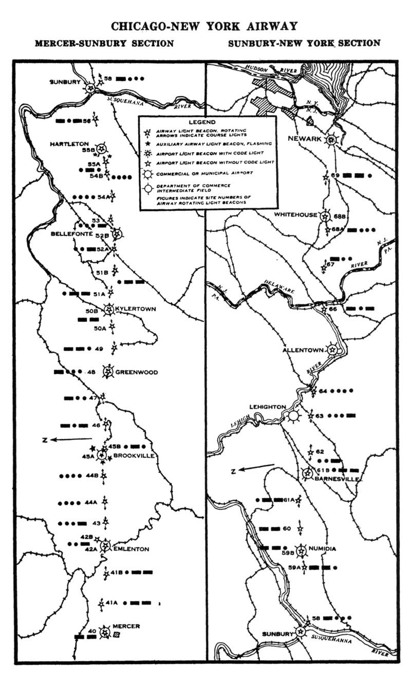
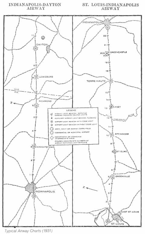
Henderson saw what was needed. “An airway exists on the ground, not in the air”. A 1923 experiment conducted by the Army Air Corps in Ohio showed that pilots could navigate at night using rotating light beacons. With this example, Henderson was able to press his requests for the development of a similar system for the Air Mail routes. Congress, in 1923, approved funding for the lighting of the Transcontinental Air Mail Route. Work started immediately on the Cheyenne to Chicago segment. Being in the middle of the nation, flights starting at daybreak on the coasts would be able to fly to either end of the lighted segment before dusk.
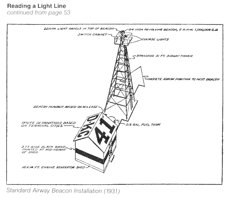
Standard Airway Beacon installation (1931) St. Louis, Missouri to Dayton, Ohio via Indianapolis
What resulted was the first ground based civilian navigation system in the world. Beacons were positioned every ten miles along the airway. At the top of a 51-foot steel tower was a 1 million candlepower-rotating beacon. Pilots could see the clear flash of light from a distance of 40 miles. Also at the top of the tower were two color-coded 100,000 candlepower course lights. These pointed up and down the airway. They were colored green, signifying an adjacent airfield, and red, signifying no airfield. The course lights also flashed a Morse code letter. The letter corresponded to the number of the beacon within a 100-mile segment of the airway. To determine their position, a pilot simply had to remember this phrase – “When Undertaking Very Hard Routes, Keep Direction By Good Methods” – and know which 100-mile segment they were on.
Standard Airway Beacon installation (1931)
The beacons were also built to aid daytime navigation. Each tower was built on an arrow shaped concrete slab that was painted yellow. The arrow pointed to the next higher numbered beacon. An equipment/generator shed next to the tower had the beacon number and other information painted on the roof.
Regular scheduled night service on the Transcontinental Air Mail Route started on July 1, 1924. Now operating around the clock, Air Mail was able to cross the nation in 34 hours westbound and 29 hours eastbound. By the fall of 1924, the lighted segment extended from Rock Springs, WY to Cleveland, OH. By the summer of 1925, it extended all the way to New York.
An English aviation journalist, visiting the U.S. in 1924, wrote, “The U.S. Post Office runs what is far and away the most efficiently organized and efficiently managed Civil Aviation undertaking in the World.”
On July 1, 1927, the U.S. Post Office ended its Air Mail operation. The Transcontinental Air Mail Route, and other air mail routes, were turned over to the fledgling Airways Division in the Commerce Department’s Bureau of Lighthouses. The Airways Division continued with the development of lighted airways. An improved version of the beacon was fielded in 1931.
On January 29, 1929, the rotating beacon at Miriam, NV was turned on, lighting the last beacon in the Transcontinental Air Mail Route.
By 1933, the Federal Airway System operated by the Airways Division comprised 18,000 miles of lighted airways containing 1,550 rotating beacons and 236 intermediate landing fields. Air Mail pilots routinely navigated the skies during the night, following the “signposts” of the rotating beacons.
About the author …
John joined the FAA in 1984 and has been an Academy instructor since 1991. He taught primarily in the Flight Service Initial Qualification and En Route Flight Advisory Service programs. He has also taught in the International and the Air Traffic Basics training programs at the FAA Academy.
History has been an interest and hobby since childhood, when he lived near many Revolutionary War and Great Rebellion battlefields and sites. His hobby became a part time job for a while as a wing historian for the U.S. Air Force Reserve.
John’s first major historical project for the FAA was to help mark the 75th Anniversary of Flight Service in 1995.
This page contains a brief history about the development of air traffic data communications.
One thing man developed early was written communications. The ability to write down information so it could be used later was a milestone in civilization. The next logical step was an efficient means of communicating this information to someone else someplace else.
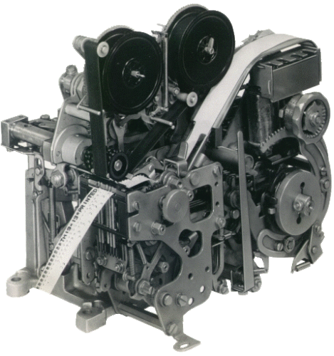
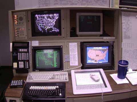
Model 28 ASR The Model 28 ASR (Automatic Send-Receive). Note the keyboard on right. The small window to the left of the keyboard shows the baudot tape. To the left of the window – the flat silver area – is the Transmission Distributor (TD)
The developing air traffic service of this century was no different. Communicating information through a nationwide system had to be accomplished in order to help aviation grow.
The early Air Mail Radio Stations (AMRS) of the 1920s used radio telegraphy to communicate with each other. The information was written by the radio operator as they translated the dots and dashes back into English. So Air Traffic’s first ‘data communications’ system was a pencil and paper and the radio. Messages on weather, aircraft positions, airfield conditions, and other information would be passed up and down the airways in this manner.
Weather information, the pilot’s main concern, was often sketchy. In the 1920s the Weather Bureau was part of the Department of Agriculture. Weather Bureau offices were located downtown in the business and government districts. Weather observations were taken there, and not at the airfield. Although the Weather Bureau was part of an extensive teletype network for collection and dissemination of weather information, the early air traffic system was not a part of their network. AMRS personnel and the pilots themselves used telephones, when available, to obtain weather information. The pencil remained an important part of the data communications system.
The Air Commerce Act of 1926 changed this situation. The Weather Bureau was tasked with provided more and better weather information to pilots. During the 1930s, as municipalities developed airports, Weather Bureau offices gradually migrated from the downtown areas to the airports.
Despite having the Weather Bureau at the airport, its teletype system remained for their sole use. Air Traffic still used the pencil in conjunction with telephones and radio telegraphy to pass information up and down the airways.
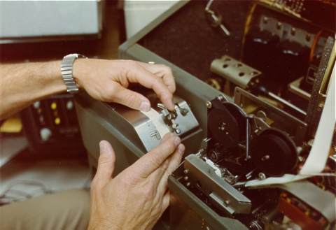
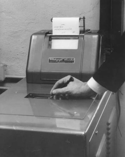
Tape Perforator Mechanism A close up of the Tape Perforator mechanism with baudot tape.
Teletype was first introduced to Air Traffic in 1928. By 1933, the national system was complete. Information on weather, aircraft positions, and airport conditions could be sent directly to any station. Many of the codes developed during the radio telegraphy days were carried over to teletype. Q Codes, as they were called, were a Morse code shorthand developed to make it easier for the radio operators to communicate. Many Q codes still exist today and are still used throughout the world.
Originally started with only one circuit dedicated to air traffic use, the system rapidly reached saturation. Another circuit was added. The alphabet was used to name the circuits. Circuit A handled only weather and NOTAM (Notices to Airmen) information. Circuit B was used for flight plans, flight notification messages, and other administrative messages. These circuits were later called services, and remain with us today as Service A and Service B.
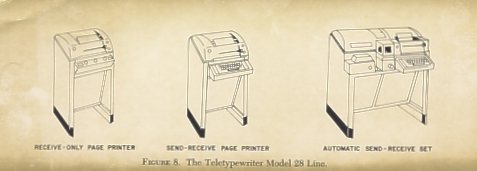
Teletypewriter Model 28 The Teletypewriter Model 28 line of equipment
Teletype was a mechanical marvel of its day, a forerunner of the computer networks that span the globe today. Imagine a vast network of equipment that had the ability to transmit and receive messages over long distances in a matter of minutes. Larger stations had equipment that could receive different messages at the same time!
An air traffic specialist would type out a message – be it a weather report, a pilot report, or an aircraft position report – on a small, customized 31 key keyboard. As the specialist typed, the Model 28 ASR (Automatic Send Receive) would perforate a small tape, similar to Wall Street’s famous “ticker tape”, called baudot tape. The tape would contain all the proper addressing, priority coding and end-of-message codes in addition to the message text. The specialist would then take the perforated tape and load it into a Transmission Distributor (TD). The TD unit would feed the tape and read the perforations. The perforations would be turned into electric impulses that would be transmitted to the addressed destination.
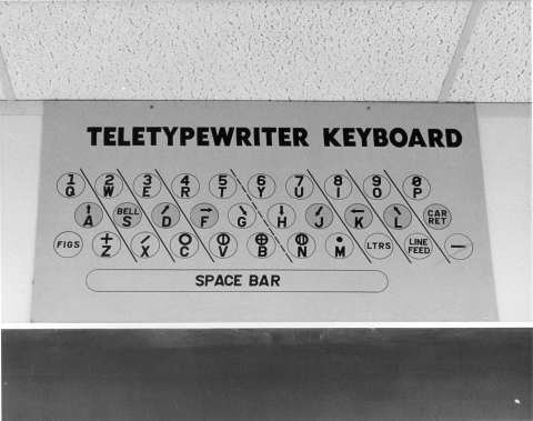
Classroom Poster A classroom poster used at the Air Traffic Academy. The arrows on the second row of keys and the symbols on the third row were used for encoding weather observations. The symbols were phased out with the introduction of LSAS – it could only use alphanumeric characters.
At the destination, the electric impulses would go into a Model 28 Printer. The message would be typed out onto a roll of yellow paper.
The teletype system, with few modifications, served the Air Traffic Service well for many years. Teletype served in Flight Service Stations into the late 1980s. Stations still using teletype received equipment from other stations that were being upgraded to use as spare parts. Equipment manufactured and purchased in the 1930s performed government service for almost fifty years. In contrast, the ‘oldest’ computer system in use with the Air Traffic Service has only seen slightly more than thirty years. Learn more about the teletype and fonts. Learn more about the teletype and fonts
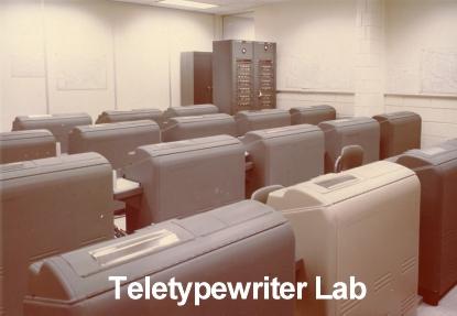
FAA Academy Teletype Lab The teletype lab at the FAA Air Traffic Academy where Flight Service specialists learned the basics of teletype. Teletype instruction finally ended in October 1985.
The introduction of radar in the en route centers in the late 1950s and early 1960s opened the door to computerization. The computers were first used to run the radars. Terminal radar systems, starting in the early and mid 1960s, followed the same pattern. Flight Service remained with the teletype system for handling weather and flight plan information.
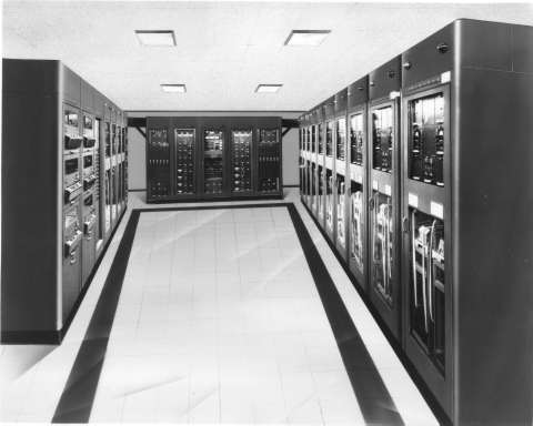
Main Frame Computer The forerunners to ‘main frames’. An example of the Automatic Data Interchange System, which exchanged large amounts of teletype messages between stations in a minimum amount of time.
Growth in air traffic and strides in computer technology called for a better way of doing business. With the air traffic system reaching saturation on an almost daily basis in 1968 and 1969, it was obvious that teletype was not a long range option. It was estimated in 1969 that to expand the current Flight Service system to meet projected 1983 traffic loads would cost $250 million dollars a year. An initial investment of $60 million for automation would significantly reduce that cost. Part of the “National Aviation System Ten Year Plan” unveiled in February 1970 called for $56 million for the reconfiguration and improvement of the Flight Service system.
Telewriter Another means of data communications within an airport. The telewriter allowed a weather observer to use a special pen and write the observation on a special pad. This handwritten message would then be printed at other locations around the airport, such as the control tower, flight service station, or airline operations office.
The long-range problem was addressed, but what about the short range? The aging teletype system wouldn’t last until the new systems came on line in the late 1970s. A short-term solution was found – blend teletype with computers.
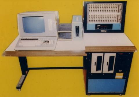
Western Union – the company that made teletype famous – built a computer based data communication system for the FAA. Called Leased Service A System – LSAS – it replaced the paper and baudot tape with CRT screens and regular keyboards. It dealt only with the Service A functions of weather and NOTAM information. Controllers could request weather and NOTAM information by typing commands on the keyboard. The reply would be displayed on the screen. A printer was part of the system so controllers could print out seldom changing reports, such as Area Forecasts and Winds Aloft Forecasts.
LSAS The position equipment of LSAS and later LABS
Running the facility system and linking it into the national system was a computer console called a GS 200. The LSAS was lightning fast compared to the slow mechanical circuits of teletype. Weather reports and forecasts were available in a matter of minutes compared to the slower transmission of grouped reports – called polls – that came over the teletype. Flight plans and other traffic related messages remained on teletype, though.
GS 200 The GS 200, the unit that linked the Flight Service Station to the national Service A and B systems. This unit allowed the supervisor to reconfigure or restart the facility as required.
Running the facility system and linking it into the national system was a computer console called a GS 200. The LSAS was lightning fast compared to the slow mechanical circuits of teletype. Weather reports and forecasts were available in a matter of minutes compared to the slower transmission of grouped reports – called polls – that came over the teletype. Flight plans and other traffic related messages remained on teletype, though.
Later the system was upgraded to include traffic messages on Service B. The blended system, called Leased A and B Service – LABS, finally retired the teletype equipment from air traffic. Flight plans and movement messages could be typed directly on to a CRT screen at a dedicated Service B position and transmitted from the same screen. Incoming messages printed automatically on a dedicated printer. Weather briefers, though, still used the paper forms as they copied flight plans from pilots. The completed form would be passed to the person on the Service B position. LABS had eliminated some, but not all of the paper used in Flight Service.
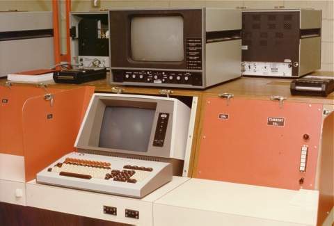
Western Union Western Union equipment at the FAA Air Traffic Academy. This position is for LSAS, used for pilot weather briefing training. The unit on top is a closed circuit TV set for viewing weather charts.
Part of the 1970 plan called for consolidation in addition to modernization of Flight Service. A final number of 61 was fixed for Automated Flight Service Stations (AFSS) to replace the almost 400 flight service stations then in existence. Modernization through computers would allow controllers to provide more and better services at a fraction of the cost.
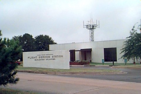
McAlester AFSS McAlester, Oklahoma AFSS
The Modernization Plan called for three separate ‘models’ to be phased in during the consolidation process. Model One was the first to combine Service A and B at the same position. Flight Services controllers could now provide weather information and file flight plans from the same position, all without paper. The computer could link the two functions together, providing a customized display of weather information tailored to the route on the stored flight plan. The first Model One facility – Bridgeport Automated Flight Service Station – opened its doors on March 3, 1984. The ‘paperless era’ of air traffic had finally begun in Flight Service.
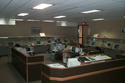
Fairbanks AFSS Fairbanks, Alaska operations floor
The Flight Service Consolidation and Modernization Program was finally completed on September 30, 1997, when the last two Flight Service Stations (FSS) were closed.
Changing costs and technologies modified the original FSS Consolidation and Modernization Plan. The Model One system was upgraded and renamed Model 1 Full Capacity (M1FC). It incorporated many suggestions from the controllers who used the Model One system.
Model One Full Capacity A typical Model One position in an AFSS
The explosion of computer technology in the mid and late 1980s opened up new and better ways of doing business by computer. The next generation of data communications was proposed using ‘off the shelf’ equipment instead of expensive custom designed systems. Called OASIS, for Operational and Supportability Implementation System, it is scheduled for deployment to Flight Service in 2000.
OASIS Equipment Future OASIS console to be installed in all AFSS facilities
Flight Service controllers maintain their heritage daily at the Automated Flight Service Stations across the country. At each computer position some paper and a pencil is maintained for those who still do some business “the old fashioned way.”
Above article written by John Schamel
About the author …
John joined the FAA in 1984 and has been an Academy instructor since 1991. He taught primarily in the Flight Service Initial Qualification and En Route Flight Advisory Service programs. He has also taught in the International and the Air Traffic Basics training programs at the FAA Academy.
History has been an interest and hobby since childhood, when he lived near many Revolutionary War and Great Rebellion battlefields and sites. His hobby became a part time job for a while as a wing historian for the U.S. Air Force Reserve.
John’s first major historical project for the FAA was to help mark the 75th Anniversary of Flight Service in 1995.
1948 U.S. Army Air Force Covers San Jose, Guate.- Panama, Panama. 14.5”x 59”
1948 U.S. Army Air Force Covers Vera Cruz, Mexico.-San Jose, Guate. 14.5”x 39.5”
1948 Covers Atlanta, GA.-Dallas- Ft. Worth, TX. 14.5”x 58.5”
1948 Covers El Paso, TX.- Los Angles, CA. 14.5”x 50.5”
1948 Covers El Paso, TX.-Dallas, TX. 14.5”x 45”
1948 Covers Jacksonville, FL.- New Orleans, LA. 14.5”x 44.5”
1947 U.S. Army Air Force Covers Barranquilla, Col. – Caracas, Venz. 14.75”x 44.5”
1949 U.S. Army Air Force Covers Caracas, Venz.-Trinidad, British West Indies. 14.5”x 44.75”
1949 U.S. Air Force Covers Talara, Peru- Bogotá, Col. 19.5”x 59”
1948 U.S. Air Force Covers Talara, Peru- Lima, Peru. 19.25”x 44.75”
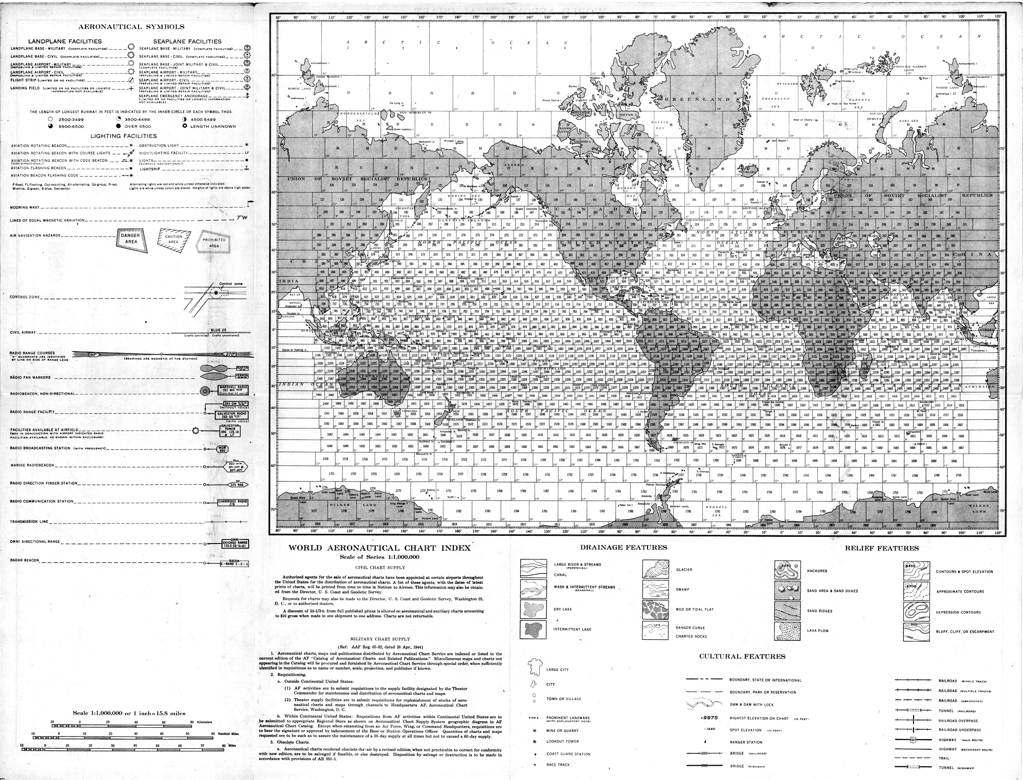
MISCELLANEOUS CHARTS
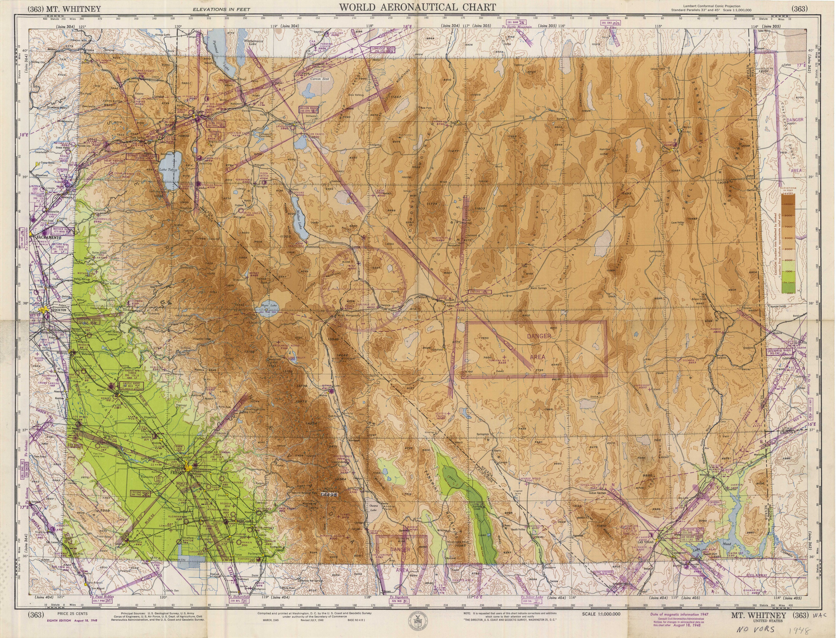
1941 Low Frequency Airway Aeronautical Planning Chart conterminous U.S. 14.5”x 45” scale 1:500,000
1949 Aeronautical Chart for Radio Direction Finding –Covers San Francisco, CA-Denver, CO.-El Paso, TX. 27.75”x36.75”
1936 Aeronautical Map of Tennessee-Covers entire state shows radio ranges, lighted airway and geology. 15”x51.25”
1944 Air Navigation Chart- Mercator Projection-Covers eastern Mex.-south, TX.-south, FL. and Caribbean. 35.5”x 54” scale 1:1,000,000
1948 Army Air Force Aeronautical Chart (like WAC) Covers Paracas Peninsula, Peru 22”x 28.5”
1943 U.S. Navy Aviation Chart – Mercator Projection-Covers Panama, Pan.-Guantanamo, Cuba. 35.75”x 54” scale 1: 1,000,000
1943 Air Navigation Chart-Mercator Projection-Covers Part of Honduras-all of Nicaragua, Costa Rica, Panama-Parts of Colombia and western Ecuador. 35.5”x54” scale 1:1,000,000

 Light Line Tower